
Lesson 05
【Arduino連携編 その5】
こんにちは、管理人のomoroyaです。
Lesson 01、02、03、04にてサンプルスケッチを利用してProcessingとArduinoを連携して遊びました。


Lesson 05も引き続きサンプルスケッチを利用して遊んでいきます。
しばらくは、どんなことができるのか体験です。
もう少しProcessingの構文の学習はおいておきます!
本日も内容理解は全て吹っ飛ばし、まずはどんなことができるのか体験です。
では、さっそく行って見ましょう。
Processingを始めようと考えている方。
ネット情報のみでも十分に学習可能です。
手元に参考書がほしいと考えている場合は下記の2冊程度で十分と考えます。


はじめに
本LessonでもLesson 01、Lesson 02、Lesson 03、Lesson 04同様にArduinoの「スケッチ例」にあるサンプルを利用します。
※統合環境であるIDEには、いくつかのサンプルスケッチがあります。
サンプルスケッチを読み出して実行するだけで、
「Arduino」と「Processing」を連携して遊ぶことができます。
どんなことができるのか確認するにはちょうど良い内容です。
公式ホームページのチュートリアルに説明があります。

上記ページの「Built-In Examples」⇒「4. Communication」と移動してください。
Communication用のTutorialが色々あります。
この中から、Processingと連携できるサンプルスケッチを選んで遊びます。
1.サンプルスケッチで遊ぶ。
2.どんなことができるのか体験する。
3.やってみたいことを想像する。
その後、本格的に学習していきます。
本Lessonでは、「4. Communication」にある「Serial Call Response ASCII」で遊びます。
このチュートリアルはLesson 04と同じ回路となります。
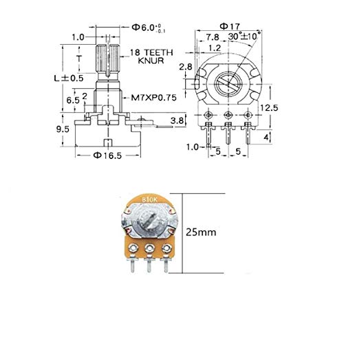
使用する電子部品は「スイッチとポテンショメータ(可変抵抗器)2つ」。
手持ちがない方は以下からどうぞ。
スイッチ1つだけ購入は、なかなか難しいです。


ポテンションメータも単品での購入はできないです。
そのため、購入される場合は種類が異なる物が入ったセットをおすすめします。
後々使い勝手が良いです。
タイプは好みで、つまみあり、なし。


上記が在庫切れの場合は下記なども。
「Serial Call Response ASCII」で遊ぶための回路
公式の英語サイトを読まなくてもできるように本Lessonでは解説していきます。
英語が気にならない場合、公式ページを読んでいただいて遊ぶことができます。
先ほどの公式ページに実体配線図も記載されています。
本Lesson、Lesson 04とスケッチを比べてみることをおすすめします。
あ~たしかに、2つの方法があるね。
とあらためて学習できる内容となっています。
では、さっそく解説。
Lesson 04とほぼ同じですが、送信方法に注目です!
公式ホームページでは、スイッチ1つと抵抗1つ。
ポテンションメータ?2つと抵抗2つを使用している実体配線図になっています。
Lesson 04同様にスイッチ1つ、抵抗1つ、ポテンショメータ2つのみとします。
部品が少なくて済みますし、これでも支障ありません。
Lesson 04とほぼ同様な動作となります。
- 起動時のみArduinoから”0,0,0”を送信
- パソコン側から応答が得られるまで待つ
- 何か文字を受信したら、センサ値を送信
3つのセンサとは以下。(Lesson 04と同じ)
- スイッチのオン、オフ検出(デジタル入力2番ピン)
- ポテンショメータ、X軸検出(アナログ入力A0ピン)
- ポテンショメータ、Y軸検出(アナログ入力A1ピン)
ブレッドボード上の電子部品の動作もLesson 04と同じ。
- スイッチを押すと、画面に白丸が現れる
- A0に繋がった可変抵抗器を動かすとX方向⇆に動く
- A1に繋がった可変抵抗器を動かすとY方向⇅に動く
というように、Lesson 04との違いがわかりません。
Lesson 04と何が違うのか?
違いは送信方法!
データの送信方法の学習には持ってこいの内容です。
ぜひ、スケッチ見比べてください。
Lesson 04、Lesson 05
管理人、学習に向いたとてもよいチュートリアルだと考えます。
Lesson 04は「Serial.write」
⇒ 1byteのバイナリデータで送信
1byteのバイナリデータで送信するために、analogRead()関数で読み取った値を4で割ってから送信しています。
1byteで送信できる数値 = 0~255
0~1023の値を4でわることで0~255のバイナリデータとして送信しています。
アナログ入力、アナログデジタル変換に関しては下記を参照ください。

Lesson 05は「Serial.print」
⇒ 数値をあらわす文字として送信
メリットは何かということですが、文字列で送信することで255よりお大きい値を簡単に送ることができます。
analogRead()で読み取った0~1023の値を文字列としてそのまま送信できます。
その後、エンコードすることで数値として扱います。
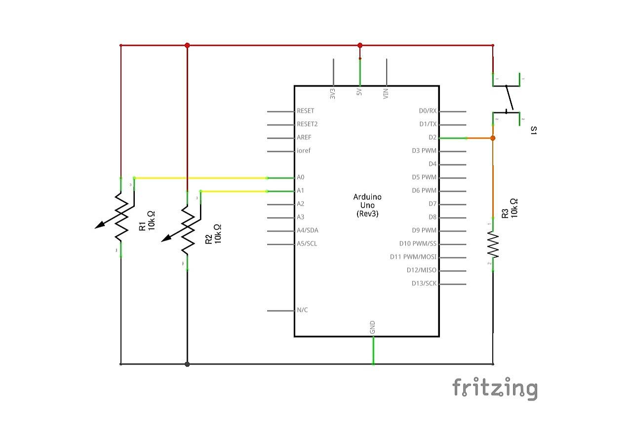
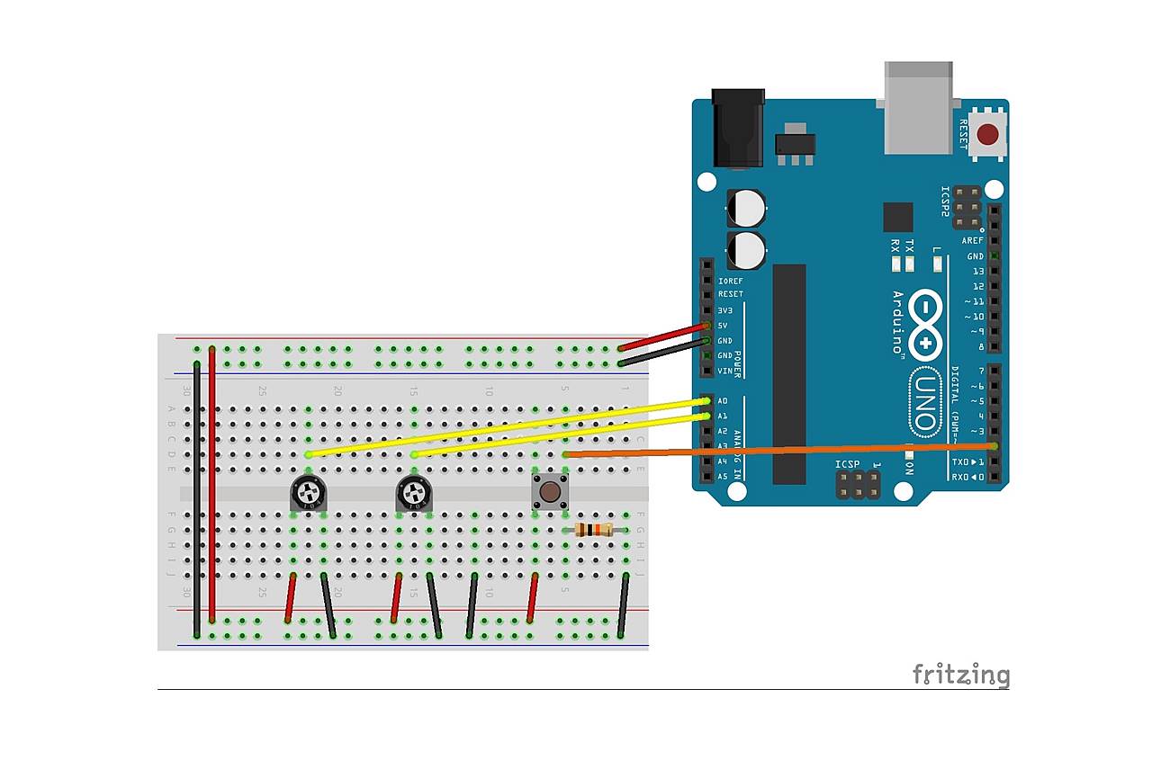
「Serial Call Response ASCII」に対応した回路図とブレッドボード図がこちらとなります。
※Lesson 04と同じです。
管理人がFrizingを使って描いた回路図となります。
「Serial Call Response ASCII」サンプルスケッチ 読み出し
Arduinoの「IDE」を立ち上げてください。
以下で「Serial Call Response ASCII」のサンプルスケッチが読み出されます。
「ファイル」⇒「スケッチ例」⇒「04.Communication」⇒「SerialCallResponseASCII」
こちらが読み出したサンプルスケッチ。
下記サンプルスケッチはArduino用のスケッチとProcessing用のスケッチが両方記載されています。
Processing用のスケッチはコメントアウトされていますので、Processingの「IDE」にコメントアウトされた部分を記載すればよいだけとなります。
/*
  Serial Call and Response in ASCII
  Language: Wiring/Arduino

  This program sends an ASCII A (byte of value 65) on startup and repeats that
  until it gets some data in. Then it waits for a byte in the serial port, and
  sends three ASCII-encoded, comma-separated sensor values, truncated by a
  linefeed and carriage return, whenever it gets a byte in.

  The circuit:
  - potentiometers attached to analog inputs 0 and 1
  - pushbutton attached to digital I/O 2

  created 26 Sep 2005
  by Tom Igoe
  modified 24 Apr 2012
  by Tom Igoe and Scott Fitzgerald
  Thanks to Greg Shakar and Scott Fitzgerald for the improvements

  This example code is in the public domain.

  http://www.arduino.cc/en/Tutorial/SerialCallResponseASCII
*/

int firstSensor = 0;    // first analog sensor
int secondSensor = 0;   // second analog sensor
int thirdSensor = 0;    // digital sensor
int inByte = 0;         // incoming serial byte

void setup() {
  // start serial port at 9600 bps and wait for port to open:
  Serial.begin(9600);
  while (!Serial) {
    ; // wait for serial port to connect. Needed for native USB port only
  }


  pinMode(2, INPUT);   // digital sensor is on digital pin 2
  establishContact();  // send a byte to establish contact until receiver responds
}

void loop() {
  // if we get a valid byte, read analog ins:
  if (Serial.available() > 0) {
    // get incoming byte:
    inByte = Serial.read();
    // read first analog input:
    firstSensor = analogRead(A0);
    // read second analog input:
    secondSensor = analogRead(A1);
    // read switch, map it to 0 or 255
    thirdSensor = map(digitalRead(2), 0, 1, 0, 255);
    // send sensor values:
    Serial.print(firstSensor);
    Serial.print(",");
    Serial.print(secondSensor);
    Serial.print(",");
    Serial.println(thirdSensor);
  }
}

void establishContact() {
  while (Serial.available() <= 0) {
    Serial.println("0,0,0");   // send an initial string
    delay(300);
  }
}

/* Processing code to run with this example:

  // This example code is in the public domain.

  import processing.serial.*;     // import the Processing serial library
  Serial myPort;                  // The serial port

  float bgcolor;      // Background color
  float fgcolor;      // Fill color
  float xpos, ypos;         // Starting position of the ball

  void setup() {
    size(640, 480);

    // List all the available serial ports
    // if using Processing 2.1 or later, use Serial.printArray()
    println(Serial.list());

    // I know that the first port in the serial list on my Mac is always my
    // Arduino board, so I open Serial.list()[0].
    // Change the 0 to the appropriate number of the serial port that your
    // microcontroller is attached to.
    myPort = new Serial(this, Serial.list()[0], 9600);

    // read bytes into a buffer until you get a linefeed (ASCII 10):
    myPort.bufferUntil('\n');

    // draw with smooth edges:
    smooth();
  }

  void draw() {
    background(bgcolor);
    fill(fgcolor);
    // Draw the shape
    ellipse(xpos, ypos, 20, 20);
  }

  // serialEvent method is run automatically by the Processing applet whenever
  // the buffer reaches the  byte value set in the bufferUntil()
  // method in the setup():

  void serialEvent(Serial myPort) {
    // read the serial buffer:
    String myString = myPort.readStringUntil('\n');
    // if you got any bytes other than the linefeed:
    myString = trim(myString);

    // split the string at the commas and convert the sections into integers:
    int sensors[] = int(split(myString, ','));

    // print out the values you got:
    for (int sensorNum = 0; sensorNum < sensors.length; sensorNum++) { print("Sensor " + sensorNum + ": " + sensors[sensorNum] + "\t"); } // add a linefeed after all the sensor values are printed: println(); if (sensors.length > 1) {
      xpos = map(sensors[0], 0, 1023, 0, width);
      ypos = map(sensors[1], 0, 1023, 0, height);
      fgcolor = sensors[2];
    }
    // send a byte to ask for more data:
    myPort.write("A");
  }

*/
「Serial Call Response ASCII」 Arduino用のスケッチを抜き出し
Arduino用のスケッチ部分のみを抜き出したのがこちら。
下記をArduino用の「IDE」に記載してArduinoに書き込んでください。
/*
  Serial Call and Response
  Language: Wiring/Arduino

  This program sends an ASCII A (byte of value 65) on startup and repeats that
  until it gets some data in. Then it waits for a byte in the serial port, and
  sends three sensor values whenever it gets a byte in.

  The circuit:
  - potentiometers attached to analog inputs 0 and 1
  - pushbutton attached to digital I/O 2

  created 26 Sep 2005
  by Tom Igoe
  modified 24 Apr 2012
  by Tom Igoe and Scott Fitzgerald
  Thanks to Greg Shakar and Scott Fitzgerald for the improvements

  This example code is in the public domain.

  http://www.arduino.cc/en/Tutorial/SerialCallResponse
*/

int firstSensor = 0;    // first analog sensor
int secondSensor = 0;   // second analog sensor
int thirdSensor = 0;    // digital sensor
int inByte = 0;         // incoming serial byte

void setup() {
  // start serial port at 9600 bps:
  Serial.begin(9600);
  while (!Serial) {
    ; // wait for serial port to connect. Needed for native USB port only
  }

  pinMode(2, INPUT);   // digital sensor is on digital pin 2
  establishContact();  // send a byte to establish contact until receiver responds
}

void loop() {
  // if we get a valid byte, read analog ins:
  if (Serial.available() > 0) {
    // get incoming byte:
    inByte = Serial.read();
    // read first analog input, divide by 4 to make the range 0-255:
    firstSensor = analogRead(A0) / 4;
    // delay 10ms to let the ADC recover:
    delay(10);
    // read second analog input, divide by 4 to make the range 0-255:
    secondSensor = analogRead(1) / 4;
    // read switch, map it to 0 or 255L
    thirdSensor = map(digitalRead(2), 0, 1, 0, 255);
    // send sensor values:
    Serial.write(firstSensor);
    Serial.write(secondSensor);
    Serial.write(thirdSensor);
  }
}

void establishContact() {
  while (Serial.available() <= 0) {
    Serial.print('A');   // send a capital A
    delay(300);
  }
}
「Serial Call Response ASCII」 Processing用のスケッチを抜き出し
Processing用のスケッチ部分のみを抜き出したのがこちら。
下記をProcessing用の「IDE」に記載してください。
/* Processing code to run with this example:

  // This example code is in the public domain.
*/

  import processing.serial.*;     // import the Processing serial library
  Serial myPort;                  // The serial port

  float bgcolor;      // Background color
  float fgcolor;      // Fill color
  float xpos, ypos;         // Starting position of the ball

  void setup() {
    size(640, 480);

    // List all the available serial ports
    // if using Processing 2.1 or later, use Serial.printArray()
    println(Serial.list());

    // I know that the first port in the serial list on my Mac is always my
    // Arduino board, so I open Serial.list()[0].
    // Change the 0 to the appropriate number of the serial port that your
    // microcontroller is attached to.
    myPort = new Serial(this, Serial.list()[0], 9600);

    // read bytes into a buffer until you get a linefeed (ASCII 10):
    myPort.bufferUntil('\n');

    // draw with smooth edges:
    smooth();
  }

  void draw() {
    background(bgcolor);
    fill(fgcolor);
    // Draw the shape
    ellipse(xpos, ypos, 20, 20);
  }

  // serialEvent method is run automatically by the Processing applet whenever
  // the buffer reaches the  byte value set in the bufferUntil()
  // method in the setup():

  void serialEvent(Serial myPort) {
    // read the serial buffer:
    String myString = myPort.readStringUntil('\n');
    // if you got any bytes other than the linefeed:
    myString = trim(myString);

    // split the string at the commas and convert the sections into integers:
    int sensors[] = int(split(myString, ','));

    // print out the values you got:
    for (int sensorNum = 0; sensorNum < sensors.length; sensorNum++) { print("Sensor " + sensorNum + ": " + sensors[sensorNum] + "\t"); } // add a linefeed after all the sensor values are printed: println(); if (sensors.length > 1) {
      xpos = map(sensors[0], 0, 1023, 0, width);
      ypos = map(sensors[1], 0, 1023, 0, height);
      fgcolor = sensors[2];
    }
    // send a byte to ask for more data:
    myPort.write("A");
  }
「Serial Call Response ASCII」 サンプルスケッチの実行
実行手順が以下となります。
- Arduino用のスケッチ部分をArduino用のIDEにコピーしてArduinoに書き込み。
※回路接続のため電源供給を一旦止める。 - 回路作成しArduinoと接続。
- Arduinoへ電源供給
- Processing用のスケッチ部分をProcessing用のIDEにコピーして実行。
これで、問題なく動くはずです。
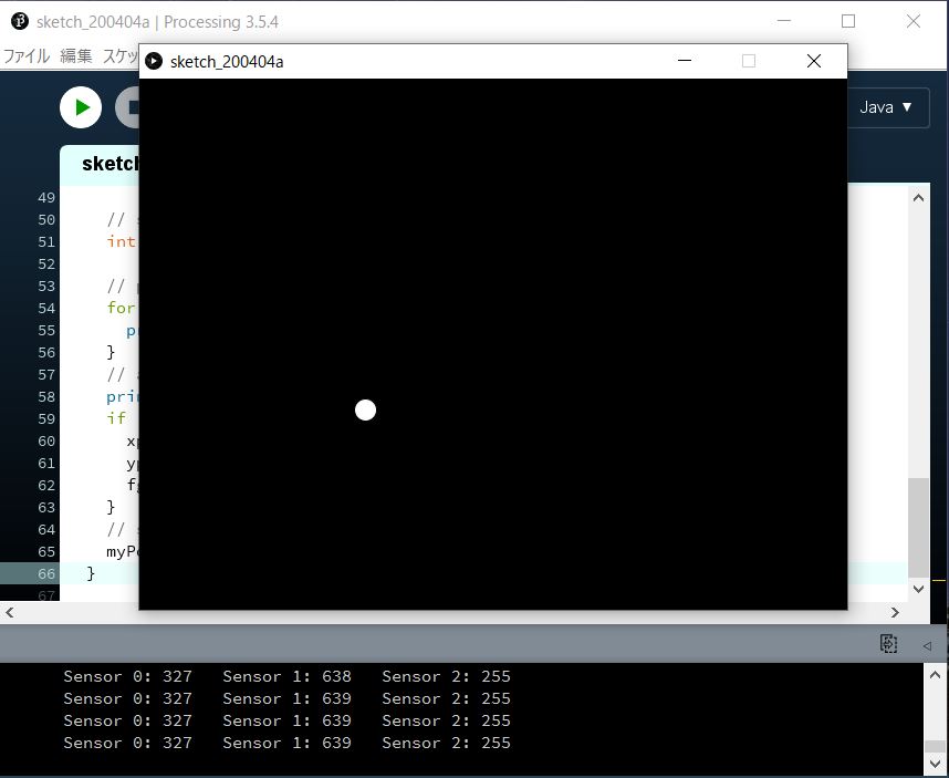
「Serial Call Response ASCII」 サンプルスケッチ実行結果
Processingを実行するとパソコンの画面中央に実行画面が現れます。
スイッチを押すと、白丸のグラフィックが現れます。
白丸を中央にするためには、ポテンショメータの出力を2.5Vとしてください。
- A0接続のポテンショメータ:白丸がX軸方向⇆に移動
- A1接続のポテンショメータ:白丸がY軸方向⇅に移動
という動作になります。
画面下の数値に注目してください。
255以上の数値でやりとりしているのがわかります。
本チュートリアルは勉強になりました。
まとめ
Lesson 05【Arduino連携編 その5】はここまで。
次回もサンプルコード使います。
最後のサンプルスケッチとなります。

Processingを始めようと考えている方。
ネット情報のみでも十分に学習可能です。
手元に参考書がほしいと考えている場合は下記の2冊程度で十分と考えます。
最後に
疑問点、質問などありましたら気軽にコメントください。
この電子部品の解説をしてほしい!などなどなんでもOKです。
リンク切れ、間違いなどあればコメントいただけると助かります。
Arduino入門編、番外編、お役立ち情報などなどサイトマップで記事一覧をぜひご確認ください。
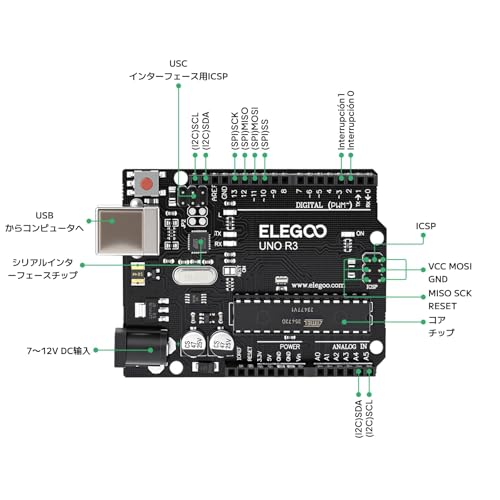
Arduino入門編、Arduino入門編2で使用しているUNOはAmazonにて購入可能です。
Arduino入門編では互換品を使用。
Arduinoはオープンソース。
複製して販売するのもライセンス的に問題なし。
そのため互換品の品質も悪くなく、それでいて値段は安いです。
正規品本体の値段程度で豊富な部品が多数ついています。
学習用、遊び用、お試し用には安価な互換品がおすすめです。
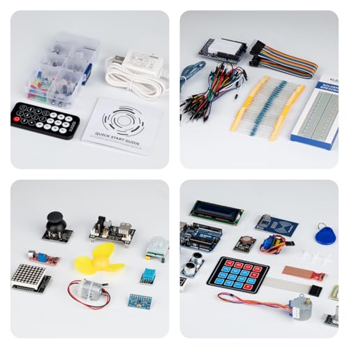
ELEGOO UNO キット レベルアップ チュートリアル付 uno mega2560 r3 nanoと互換 Arduino用


上記のものでも十分に多数の部品が入っていますが、最初からもっと多数の部品が入っているこちらもお勧めです。


Arduino入門編2では「Arduino UNO R4 Minima」「Arduino UNO R4 WIFI」にて遊ぶため今のところは正規品を使用。(まだ互換品が・・・ほぼない)


Amazonでお得に買う方法
Amazonでお得に購入するならAmazon Mastercard、Amazonギフト券がおすすめです。
時期により異なりますが、様々なキャンペーンを実施しています。
\Amazonギフト券/
Amazonギフトカード キャンペーン
\Amazon Mastercard お申込み/
Amazon Mastercard 申し込み
いずれの場合もプライム会員である方がお得!!
\Amazon Prime 30日間の無料会員を試す/
無料会員登録


コメント
記事を拝見させていただきました.
当記事内のArduino用スケッチ部分飲み抜き出したプログラムがLesson04のSerial.writeになっていると思います.ご確認いただければと思います.
コメントありがとうございます。
確かに、間違えています。
修正しました。
ご指摘いただけると助かります。
また、何かお気づきの点ありましたらよろしくお願いいたします。